Part 1) How to Oscilloscope
a) Waveform
a) Waveform
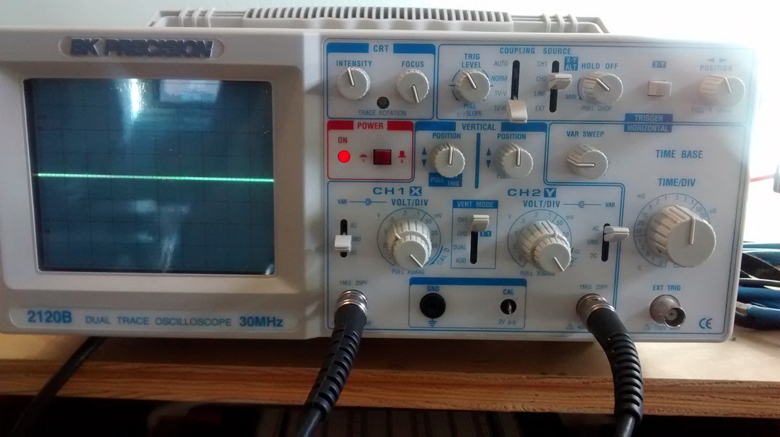
To use the oscilloscope, you would need to turn on the power, of course. The x-axis represents time, and the y-axis represents voltage. The "VOLT/DIV" knobs adjust the amount of voltage each division of y-axis represents. So for example, if the "VOLT/DIV" knob is set to .5 V, then each division of y-axis will be .5 V. The "TIME/DIV" knob adjusts the amount of time each division of x-axis represents. So if the "TIME/DIV" knob is set to 1 mS, then each division of x-axis will be 1 mS. The "POSITION" knob moves the wave up and down, and usually it should be set to the center. To connect your circuit to the oscilloscope, you connect the black probe to the ground, and the red probe to a point in your circuit. When "VERT MODE" is set to CH1, the oscilloscope will only display the wave of CH1. If it is set to CH2, the oscilloscope will only display the wave of CH2. If you want to compare the the waves of both CH1 and CH2, then "VERT MODE" should be set to DUAL.
b) Volume knob
When I turned the potentiometer, the amplitude of the output wave (ch2) increased and decreased. The minimum amplitude of the output wave is 0% of the input wave, and the maximum amplitude of the output wave is 100% of the input wave.
c) RC circuit
What I expected to happen with the RC circuit filters is that at the corner frequency the output voltage would be less than the input voltage. And for highpass filter, the output and the input would be the same for frequencies higher than the corner frequency, and the output will decrease more and more as the frequency goes below the corner frequency; and vice a versa for lowpass filter.
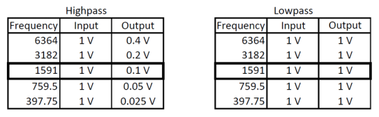
Recorded Data
But oddly, that is not what I observed. For highpass filter, although output voltage decreased as the frequency went down, the overall output voltage was too small compared to the input voltage. For lowpass filter, there was no change in the output voltage. However, I could not figure out why this happened.
Part 2) Final Project
I learned about Hurdy Gurdy in Music History, and I thought it would be cool to make an electronic hurdy gurdy. Hurdy gurdy is a stringed instrument that is played by cranking the wheel which is rubs against the strings and produces sound. It has 2 or 3 droning strings, and 1 string which you can play the melody with a keyboard.
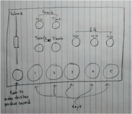
Instead of cranking the wheel, my electronic hurdy gurdy will produce sound when a button is pushed. There will be a droning sound or sounds, and the melody can be played with the keys or buttons. There will be a volume fader or a knob, 3-band EQ, tremolo or vibrato (or both perhaps), and hopefully a reverb, to tweak the sound.
Part 2) Final Project
I learned about Hurdy Gurdy in Music History, and I thought it would be cool to make an electronic hurdy gurdy. Hurdy gurdy is a stringed instrument that is played by cranking the wheel which is rubs against the strings and produces sound. It has 2 or 3 droning strings, and 1 string which you can play the melody with a keyboard.
Instead of cranking the wheel, my electronic hurdy gurdy will produce sound when a button is pushed. There will be a droning sound or sounds, and the melody can be played with the keys or buttons. There will be a volume fader or a knob, 3-band EQ, tremolo or vibrato (or both perhaps), and hopefully a reverb, to tweak the sound.
 RSS Feed
